FAQs
- What's Covered under the LEED Brakes Warranty?
- How do I bench bleed my master cylinder?
- Why is my brake pedal is low or spongy?
- How To Calculate Pedal Ratio
- How do I test my vacuum power brake booster
- Proportioning Valve Brake Line Routing
- Do you have a Power Booster & Master Cylinder Installation Guide?
Q: What's Covered under the LEED Brakes Warranty?
Limited Warranty
THE WARRANTIES AND REMEDIES CONTAINED HEREIN ARE EXCLUSIVE AND IN LIEU OF ALL OTHER WARRANTIES EXPRESS, IMPLIED, OR STATUTORY, INCLUDING ANY LIABILITY ARISING UNDER ANY WARRANTY OF MERCHANTABILITY OR FITNESS FOR A PARTICULAR PURPOSE, STATUTORY OR OTHERWISE. THIS WARRANTY GIVES YOU SPECIFIC LEGAL RIGHTS, WHICH MAY VARY FROM STATE TO STATE.
IN NO EVENT SHALL LEED Brakes BE LIABLE FOR ANY INCIDENTAL, SPECIAL, INDIRECT, OR CONSEQUENTIAL DAMAGES, WHETHER RESULTING FROM THE USE, MISUSE, OR INABILITY TO USE THIS PRODUCT OR FROM DEFECTS IN THE PRODUCT. Some states do not allow the exclusion of incidental or consequential damages, so the above limitations may not apply to you. LEED Brakes retains the exclusive right to repair or replace (with a new or newly-overhauled replacement product) the device at its sole discretion. SUCH REMEDY SHALL BE YOUR SOLE AND EXCLUSIVE REMEDY FOR ANY BREACH OF WARRANTY. Note: LEED Brakes reserves the right to change or discontinue any program upon thirty (30) day written notice. All references to credits, programs, payments and prices are in U.S. dollars.
Q: How do I bench bleed my master cylinder?
Bench bleeding your master cylinder is one of the most important steps in bleeding your brake system. If you do not properly bleed your master cylinder in a vice off the vehicle you will not be able to remove all the air from your vehicles braking system.
Follow the steps below to ensure you start with a master cylinder free of any air.
- Place your master cylinder in a vice, ensure that it is level and you have clear access to the piston.
- Attach a piece of clear plastic hose to the short end of one of the plastic nozzles, follow this same step for the other hose and nozzle.
- Clip the plastic “bridge” to the wall and push the ends of the hoses through the holes so they will be completely submerged in brake fluid once fluid is added. One hose for each reservoir, if bleeding a single bowl master cylinder you will need one hose for each port on the master cylinder.
- Press the tapered end of the nozzles firmly into the cylinder port holes with a twisting motion.
- Fill the master cylinder with clean brake fluid recommended by the manufacturer. If using Silicone fluid STOP and read the disclaimer below before proceeding.
- Using full strokes, slowly push the pistons in then release back. Do this until ALL the air bubbles have disappeared from the tubes and reservoir. ** Hoses MUST remain submerged in brake fluid until bleeding process is complete otherwise you will not be able to remove the air from the master cylinder.
- Remove the hoses from the reservoir leaving them attached to the ports. Plug or tie off the hoses to keep them from leaking fluid. Replace the master cylinder cap and install the master cylinder on the vehicle. USE CAUTION as brake fluid can severely damage any painted surfaces. Install all brake lines to the master cylinder one at a time being careful not to spill any brake fluid.
- Once your lines are installed you can now bleed the rest of the system. You must be very careful not to introduce air back in the system with the air that is trapped in the brake lines. There are several ways to bleed your brake system. We recommend gravity bleeding the system in which you remove the master cylinder lid and simply open the right rear brake bleeder and let the fluid flow naturally. If your system is working properly with no restrictions you will get a good drip of fluid. After a few minutes, close that bleeder then move to the left rear, then right front and finally the left front. During this procedure you must keep an eye on the master cylinders fluid level. If the master cylinder goes dry you must start the bench bleeding process over. Next it is safe to depress the brake pedal several times until the brake pads make full contact with the friction surface. Once that is completed you must gravity bleed the system one more time until all the air is removed at each wheel.
Caution:
Most Bleeder kits are only designed to be used once. If the nozzle is burred or damaged it may not seal allowing air to be drawn into the master cylinder.
Silicone Brake Fluid Caution:
While silicone brake fluid has its many advantages it also has a few weaknesses with today’s brake systems. In order to use silicone brake fluid your entire brake system must be composed of all peroxide cured EPDM seals. Silicone brake fluid will distort and break down standard rubber seals causing your system to leak and fail. Silicone usually will break down standard seals in a very short amount of time. If you are not sure if your seals are peroxide cured EPDM seals check with the component manufacturer before using silicone fluid.
Q: Why is my brake pedal is low or spongy?
Low or Soft Brake Pedal Diagnosis
Before beginning the following procedure check to make sure brake pedal free play is approximately ½” and air gap from booster pushrod to master cylinder piston is approximately .015” and all bleeders are at the top of the calipers or wheel cylinders.
1) Disconnect brake lines from master cylinder. Install plugs in ports of the master cylinder. Use plugs with tapered seat as not to damage brass seats in master cylinder ports.
2) Once plugs are installed press and hold brake pedal down firmly for 30 seconds. Does brake pedal remain steady at the top of its travel and not move at all? If YES proceed to step 5. If NO continue to next step.
3) If brake pedal seems spongy or pushes back at you while being applied you most likely have air in the master cylinder. Remove the master cylinder and re bench bleed following manufactures recommended procedure. Re install master cylinder and re test using steps above.
4) If while holding pressure on the brake pedal it seems to “sink” or “creep” to the floor the master cylinder is faulty. It will need to be replaced. Bench bleed new master cylinder following manufacturers recommended procedure and re install. Before hooking brake lines to master cylinder repeat steps 1-2 to ensure proper operation.
5) Clamp off all flex hoses on vehicle. Use caution as to not damage hoses.
6) Press and hold brake pedal down firmly for 30 seconds. Does pedal remain firm and steady? If YES proceed to step 8. If NO continue to step 7.
7) If the brake pedal is spongy, soft or “creeps” down you have an external fluid leak or air trapped at a point between the master cylinder ports and the clamps. Repair any leaks or re bleed system and re test.
8) Remove one clamp and press the brake pedal. Take note as to how it feels. Re clamp that hose and remove one other clamp and take note as to how the pedal feels again. Work your way around the car testing only one brake circuit at a time.
9) Once you find the circuit that lets the brake pedal move the most you have found the problem circuit. Inspect the brake circuit in question for an external fluid leak, excessive mechanical movement of caliper pistons or wheel cylinders, or air trapped in the circuit. Take this time to make sure the brake bleeders are at the top of the caliper or wheel cylinder and all brackets are correctly aligned and in the proper locations.
10) Perform necessary repairs/adjustments and re bleed and re test as needed.
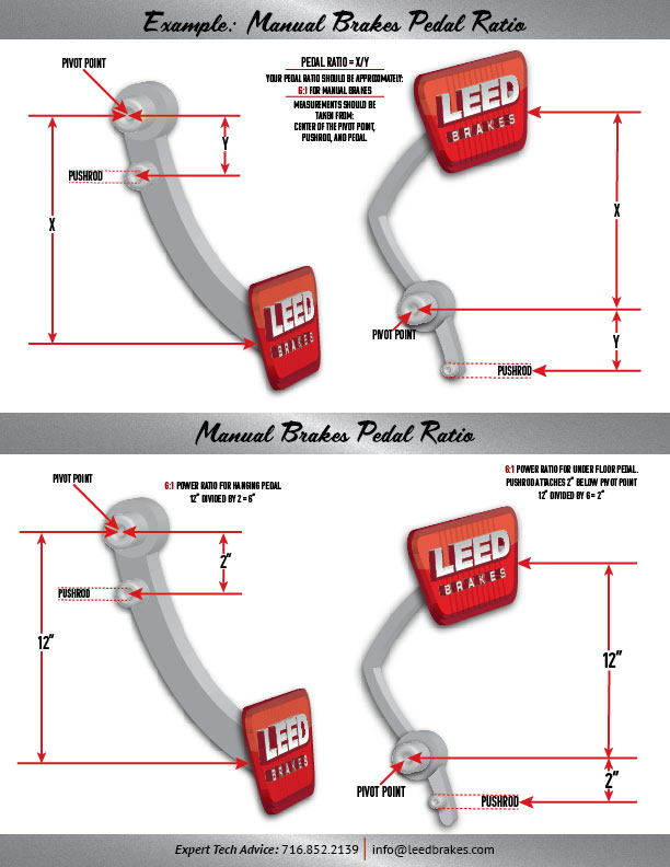
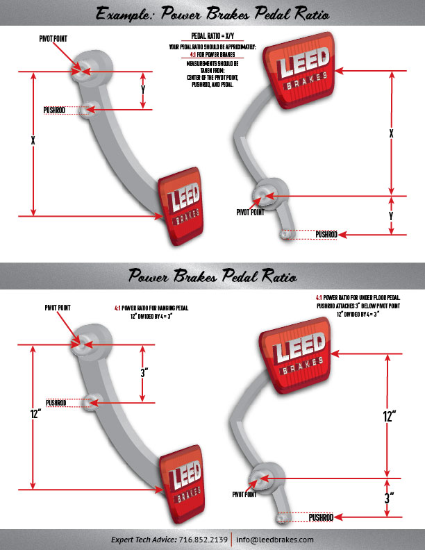
Q: How To Calculate Pedal Ratio
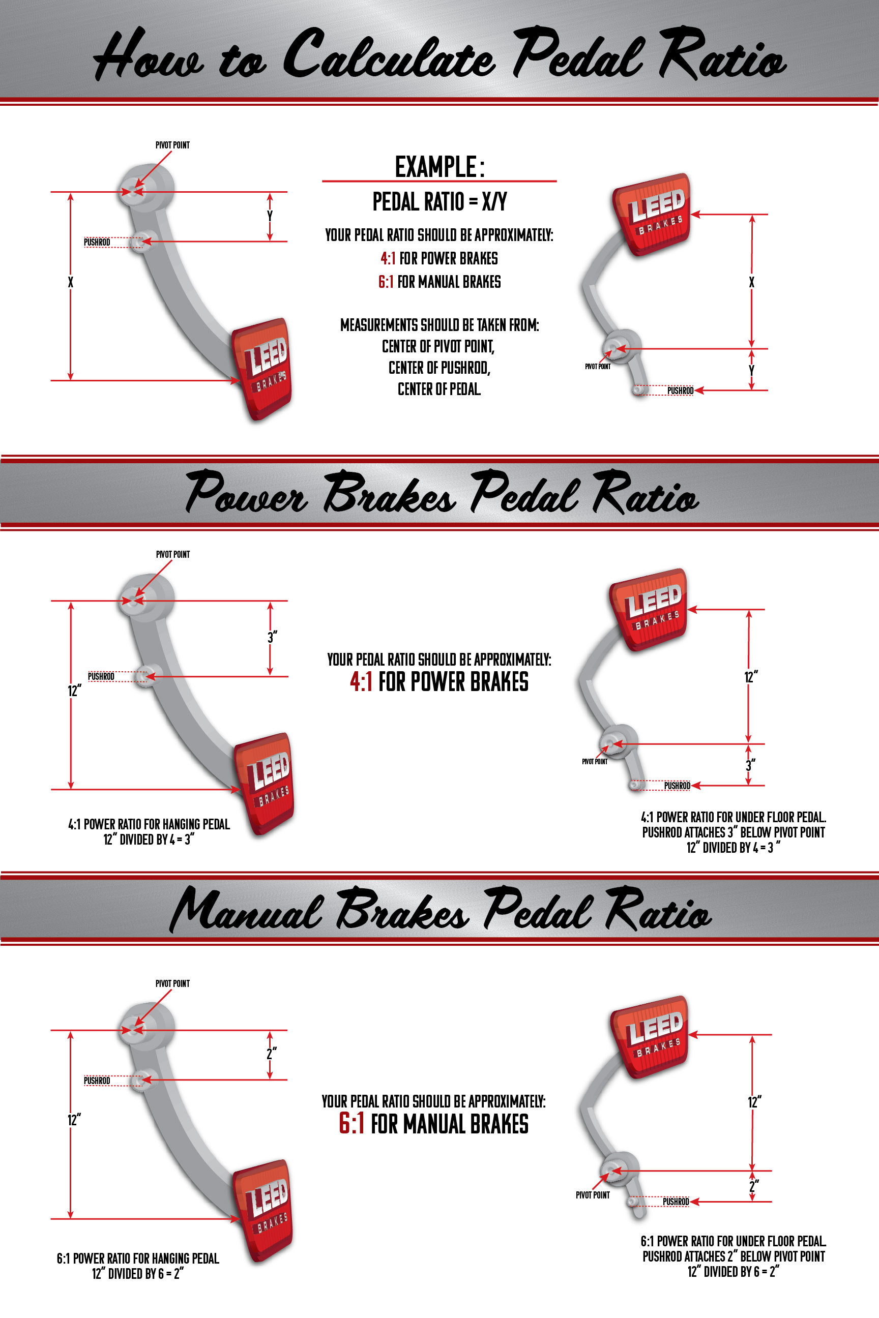
To download a printer friendly version of the diagram click the needed link below.
LEED Brakes Manual Brakes Pedal Ratio Diagram
LEED Brakes Power Brakes Pedal Ratio Diagram
Q: How do I test my vacuum power brake booster
Vacuum Brake Booster Testing and Diagnosis
Minimum engine vacuum required is 18”HG at idle in gear.
You will need a vacuum pump with a gauge to perform this procedure. Most “chain” parts stores will rent, loan or sell them.
1) Remove vacuum hose from check valve on booster. Place hose from vacuum pump onto check valve and draw booster to 20”Hg of vacuum.
2) Let booster sit with vacuum applied for 5 minutes. Vacuum should remain steady at 20”Hg. If vacuum does not stay steady at 20”Hg the booster it is faulty and will need to be replaced. If vacuum does hold steady at 20”Hg proceed to step 3.
3) With 20”Hg of vacuum in booster depress brake pedal once and release it. The booster should transfer SOME but not ALL of the vacuum. Depending on how hard the pedal is depressed it is normal to see a 5-10”Hg drop in vacuum. The most important thing is to ensure that the booster does transfer SOME vacuum but does NOT transfer all of the vacuum in its reserve. If vacuum remains at 20”Hg OR goes to zero the booster is faulty and will need to be replaced. If vacuum transfer is within the above range proceed to step 4.
4) Once again draw booster down to 20”Hg of vacuum. Depress brake pedal and hold down for 30 seconds. You should see the vacuum gauge drop slightly and then hold steady. Vacuum should stay steady as long as you are holding the pedal down. If vacuum drops while pedal is being held down the booster is faulty and will need to be replaced.
Q: Proportioning Valve Brake Line Routing
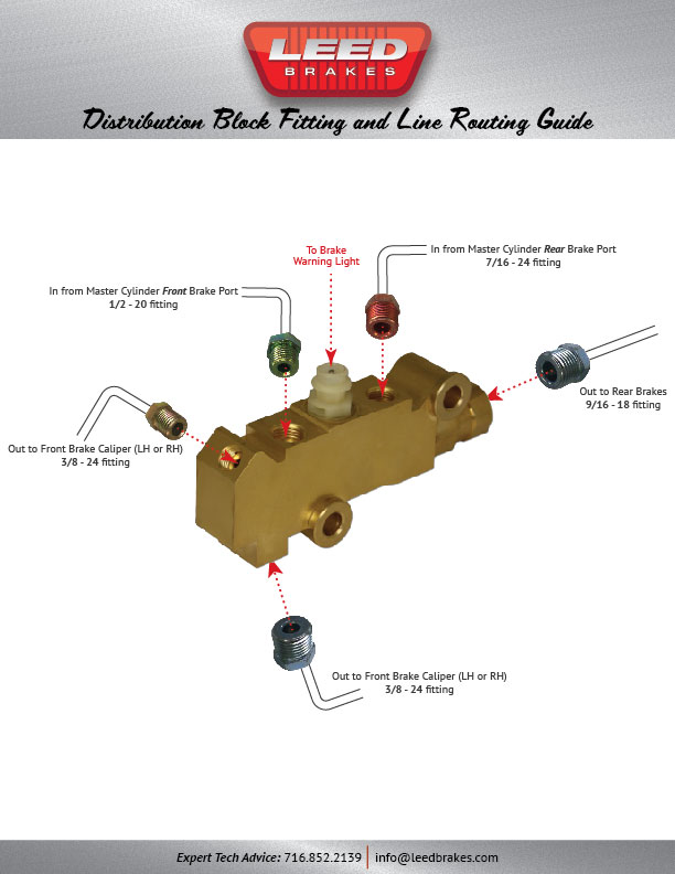
To download a printer friendly version of the Proportioning Valve Fitting and Brake Line Routing Guide click the link below.
LEED Brakes Proportioning Valve Fitting & Line Routing
Q: Do you have a Power Booster & Master Cylinder Installation Guide?
Download this guide. If you have any questions about your brake system, please call us at 716-852-2139 or send us a message at tech@leedbrakes.com